Featured post

Hello World, or In the beginning!

This July, it has been terribly warm here in Borås, Sweden, almost tropical climate.

Now, I have been terribly affected by this climate, so I obviously became insane.

So what happened really, well, I was sitting and having a Guinness and a malt, thinking of what to do.

Then I realized, I must build my self a computer, a proper one.

WTF, you probably Thinks, thats no strange with that, just take a Mobo, a Processor and some Graphics, and off you go.

Well, you could not be more wrong.

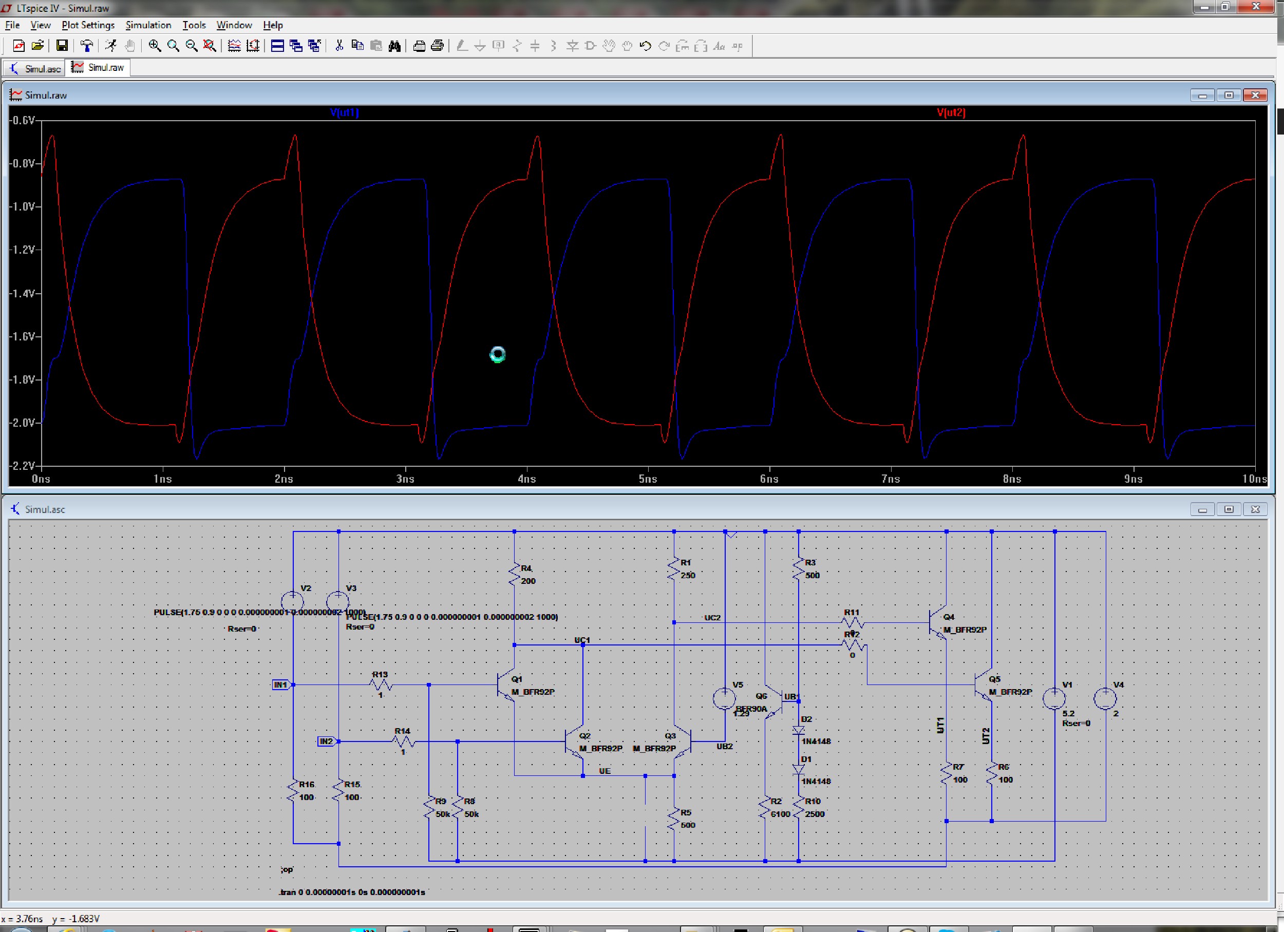
What I am going to build is a proper computer, based on pure ECL technology, like the old CRAY-1 (hense the name of the site), but I am not going to use any intergrated circuits as Samuel Cray did, but discrete bipolar technology, just plain transistors and resistors, nothing else, but loads of them, (hence the name of the site again).

I estimate that I will use about som 5-6000 transistors and the same amount of resistors, if this isn’t proof for insanity, I do not know what is.

Now I will update with schematics, simulations, thougts etc, when it happens, and at the end photos and other things.

New section, FILES

I have created a Files Section, where all schematics etc will go.

You will find it in the menu above.

Currently all schematics for the ALU is there.

Some statistics, the card will be a 4-layer card 160x230mm approx. (dual Eurocard size)

Layer stackup as follows:

  1. Signal layer and  SPL0 Plane.
  2. SPL0 Plane
  3. VTT Plane
  4. Signal layer and VEE plane

In total there are some 800 components on each card:

Some 380 Resistors, 377 transistors and 19 LED

A complete 8-bit ALU would require some 3000 resistors and some 3000 transistors.

All transistors are the same BFR92P in SOT23

The resistors are 220R, 245R, 680R and 100R, in 0805.

Power supplies: VEE = -5,2V, VTT -2V.

The Design, Part 2: The ALU.

I have nearly completed the initial design of the ALU.

There are still some bits missing, and I havent simulated the whole ALU yet, only partly att block-level

It will support the following primitive functions:

  • AND
  • OR
  • NOR
  • XOR
  • ADD
  • SUB
  • SLT

Here is a screenshot of the ALU

Schematic Editor ( Circuit _ 1-BIT_ALU - Page _ MAINPAGE ) [Project _ ECL] Page _ 1

And the more readable pdf-file Main ALU

There is also a register section, 3 registers (at the moment) one bit per slice.

Schematic Editor ( Circuit _ 1-BIT_ALU - Page _ REG ) [Project _ ECL] Page _ 1

The pdf: Registers

There is three register A, B and Result.
the registers consist of one D Flip-Flop, per gate together with demultiplexers for selecting the function

The following operations is supported, it probably will be changed in the future:

  • CPYMA (copy from Data-bus to A)
  • CPYMB
  • CPYRM ( Copy Result to Data-bus)
  • CPYRA (Copy Result to A)
  • CPYRB

When you look at the schematics, it might be a Little bit strange, but using ECL has an advantage compared to other families, The complementary output is easily accessible, which means that I can use that to reduce the number of gates needed.

For example, if I need an 2-input AND-Gate, you will use two inverters on the input of a NOR-Gate, thus, using the inverted output off the previous gate, instead of the normal output, I can omitt the inverters, saving two gates (Three transistors per gate).

This is basically what will go on each ALU-Slice Circuit board, together with the Biasing Circuit (I am also playing with the Idea of having a common Bias Circuit for the whole computer).

Apart from the above, there will also be a separate PCB for Look-Ahead Carry, as well as status register and Zero detecting Circuit.

The Design, part 1: Overview

I havent put anything in stone, yet.

Slice and so on. All connected to one or more backplanes.

The backplane will most likely be wire-wrapped, since I feel that it is the simplest way to do it.

It will probably, at least in the beginning be an 8-bit computer, memory, I dont know at the moment (future problems, probably core memory).

The physical design, well, don’t know yet, why not as a Cray1?

Anyway, the future will see.

The basics

Embarking on this journey, i realised that it was som 25+years since I went to school, so I had to recap about ECL and other things, however it wasn’t that  difficult anyway.

I began with designing the base Circuit a 2 input ECL-gate and did some simulations in LT-Spice.

I realized that the type of transistor I was going to use affected everything quite dramatically, so I started searching for a decent tranny to use.

It seems that I ends upp with something called BFR92P.

Simulating it in LT-Spice it seems that, at least in theory, I should be able to run this computer att 500 MHz.

Here is a screenshot of the simulation.

Corel309

Obviously, I realise that I would not be able to run at this frequency, as well as the problem designing a Clock oscillator with several phases with discrete Components, and furthermore, my function-genny cant go that high, only 20 MHz, so that will be the target, for now.